Applications. The switched-reluctance motor has some advantages that make it particularly suited for certain applications. The stator is a relatively low-cost component because it is easy to wind. Figure 5.105 shows a 6/4 3-phase motor with 2 poles excited. This is wound on a gun winder and is a simple series connection.
Figure 5.106 shows an 8/6 motor with 2 phases wound. Here the adjacent phases are the same polarity, and the flux goes through the rotor to the opposite poles at 180°.
Figure 5.107 shows the same stator and rotor configuration as shown in Fig. 5.106, except that the adjacent poles are connected in the opposite polarity. Here the flux goes through only the top portion of the rotor and uses only X of the stator yoke. This configuration reduces core losses, increases flux, and increases output torque. The stator yoke Wsy needs to be wider for this connection because the yoke carries all of the pole flux.
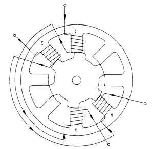
FIGURE 5.106 8/6 4-phase switched-reluctance motor.
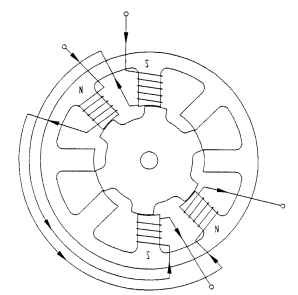
FIGURE 5.107 8/6 switched-reluctance motor with short flux paths.
These windings can be simple series connections with the controller reversing the current in the phases as necessary. An alternative is to wind two strands of wire on each pole and connect them in opposite polarities. This is called a bifilar winding. It has the advantage of using a simpler controller but has only half the space available for copper per active phase.
SRMs can be operated at relatively high speeds, which makes them candidates for hand tools, power tools, lawn care equipment, kitchen appliances, and any application where a universal motor is used. There are some applications that use battery-operated PMDC or BLDC motors that have high speed requirements that could be replaced by switched-reluctance motors.
The switched-reluctance motor has no brush commutator set; thus, it has no sparking. This opens the door for use in explosion-proof pumps.
Noise. There are, however, a few drawbacks. The SRM's small air gap and saliency lead to opportunities for noise (refer to Fig. 5.108).
As the rotor pole tips are drawn toward an energized stator pole, a force exists that attempts to bend the stator pole in the direction of the rotor pole. The rotor moves past the aligned position, starts to slow down, and is snapped to the next sta-tor pole.
This pole also attempts to bend in the direction of the rotor. The result is vibrations set up in both the rotor and the stator teeth. Further, the air gap flux in the aligned position attempts to pull the rotor and stator poles together. This causes the
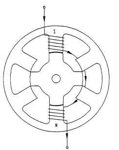
FIGURE 5.108 Cross section of switched-reluctance motor.
OD of the stator to collapse minutely, resulting in the round stack becoming slightly oval. The radial deflection A can be estimated from the pole force as follows:
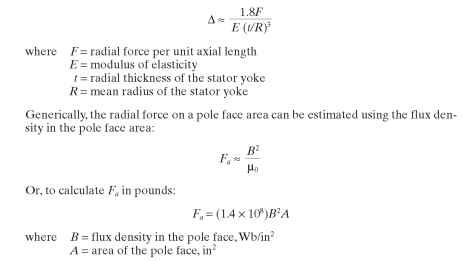
When the air gap is very small and the flux density is very high, it is possible to magnetically cause rotor-stator interference, as well as noise.
Another cause of noise is the rotor being offset in the stator bore. This results in
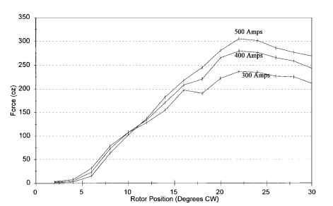
FIGURE 5.109 Force on offset rotor versus position for 2.5 OD 8/6 1.25 stack switched-reluctance motor. Rotor is offset by Lg toward one active pole. Forces with rotor centered are very small. (Data compiled using boundary element analysis software from Integrated Engineering Software.)
a shaft deflection that tends to bend the shaft in the shape of a bow. Figure 5.109 shows the increase in force or side pull at various stator currents as the rotor is offset by half the air gap length.
Some things that can be done to reduce noise are the following:
• Lower the flux density (i.e., use a longer stack).
• Increase motor mass.
• Stiffen the poles by adding large radii in the corners.
• Increase rotor inertia.
• Increase the shaft diameter to reduce deflection.
• Increase the air gap.
^ Employ control system damping schemes.
^ Keep the rotor centered in the stator.