These motors are built in a manner very similar to that for induction motors. They may have polyphase windings or be designed as single-phase motors, such as capacitor-start, split-phase, or shaded-pole types.
The rotors have a dual construction that allows for induction motor starting characteristics and salient-pole synchronous running conditions.
These rotors may be made from induction motor stampings with some of the teeth removed, as shown in Fig. 7.1.They are then die-cast in the same manner as an induction motor rotor (Fig. 7.2).
Some motors use a permanent magnet in conjunction with an induction motor rotor. Figures 7.3 and 7.4 show such a motor. This is a four-pole shaded-pole motor. Here the field coils are connected such that they directly produce two like poles and induce two opposite poles at 90° in the unwound space between the coils. In these
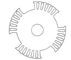
FIGURE 7.1 Induction synchronous motor lamination.
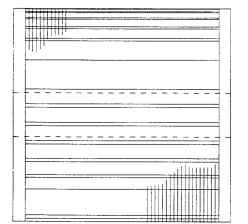
FIGURE 7.2 Four-pole induction synchronous rotor assembly.
figures, the rotor is shown to be enclosed by the stator. Figure 7.3 shows the permanent-magnet part of the rotor, while Fig. 7.4 shows the induction rotor end.
The rotor is shown alone in Figs. 7.5 and 7.6, with a piece of magnetic viewing film over the permanent-magnet portion. Figure 7.5 demonstrates the position of the magnetic poles, of which there are four on the rotor. Figure 7.6 shows that the induction rotor portion is a laminated structure with copper-wire bars swedged over copper-plate end rings.
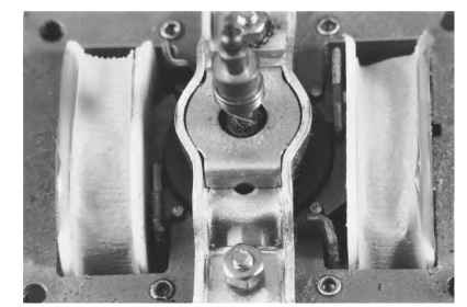
FIGURE 7.3 Shaded-pole synchronous motor, permanent-magnet rotor end.
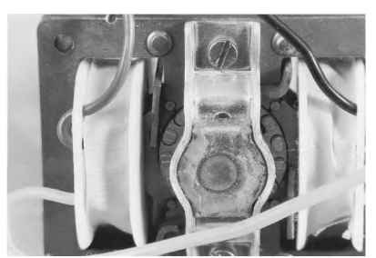
FIGURE 7.4 Shaded-pole synchronous motor, induction rotor end.
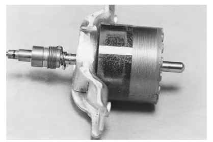
FIGURE 7.5 Shaded-pole synchronous motor showing magnetized poles.
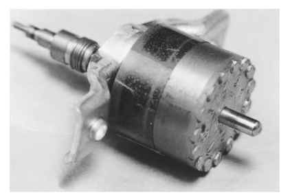
FIGURE 7.6 Shaded-pole synchronous motor rotor showing induction motor bars and end rings.