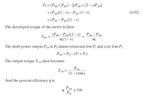
We have previously arrived at the steady-state equivalent circuit of the single-phase motor using the double-revolving-field approach. The circuit is repeated in
Fig. 6.16, with a change to more common notation—the subscript m indicates the main winding.
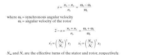
The analysis is sometimes simplified by redefining the apparent resistances and reactances of the forward and backward fields to simplify the calculations. The redrawn circuit then appears as shown in Fig. 6.17, where
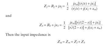
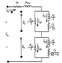
FIGURE 6.16 Single-phase motor equivalent circuit with common notation.
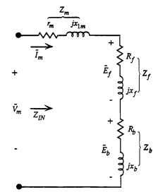
FIGURE 6.17 Simplified single-phase motor equivalent circuit.
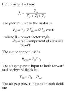

The torques developed by both forward and backward fields can now be calculated:

The rotor copper loss caused by both the forward and backward rotating fields is equal to the slip times the power transferred from stator to the rotor air gap power. Therefore:

