5.2.6
In step motors, the key to efficient performance is to match the load inertia to the step-motor rotor inertia.
TABLE 5.12 Typical Step-Motor Characteristics
| Specification | Motor type | ||
| VR | Hybrid | PM | |
| Step angle | 0.6618-30° | 0.45-5.0° | 3.75-45° |
| Phases | 3,4,5 | 2,5 | 2,4 |
| Drive type | Unipolar | Bipolar | Unipolar/bipolar |
| Rotor inertia | Low | Medium | High |

Next, size the rotor from the inertia requirement.
The rotor assembly consists of a shaft and a rotor body with salient poles on its periphery (Fig. 5.54). Since the shaft and rotor body all rotate about the same axis, the inertia J for each part may be calculated separately; then they may be added together to get the total inertia.
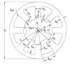
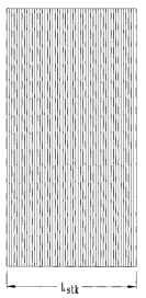
FIGURE 5.53 Variable-reluctance step-motor lamination stack.
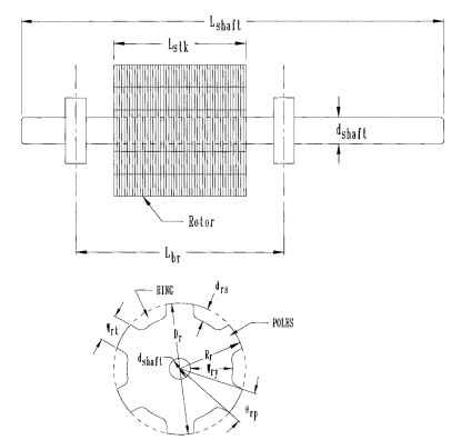
FIGURE 5.54 Rotor and stator assembly.
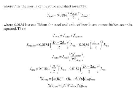
where the density of steel psteel = 4.528 oz/in3 and all inertias are in ounce-inches-seconds squared.
Since the shaft is known, calculate its inertia first and subtract it from the total allowable inertia. Then select the largest rotor diameter that is practical for the allowable motor diameter and length. The larger the diameter, the more torque available per unit length. Try to match the load inertia as reflected to the motor. At this point in the design you have not selected the drs dimension, so estimate it as 30 percent of Rr . Now that drs is known, save the rest of the allowable motor diameter for the stator. Note here that the stator OD should normally be greater than 2Dr. Now all major dimensions required to produce the torque are known except for the air gap length.
Sizing the Air Gap. The air gap length in VR step motors should be kept between 0.0015 and 0.003 inch per side. This requires very tight machining tolerances.
Selecting the Number of Phases and Poles
Three phase
• Always has positive torque
• High torque ripple
^ Poor peak torque-to-average torque ratio
^ Low number of power transistors (3 minimum)
Four phase
• Low torque ripple
^ Good peak torque-to-average torque ratio Five phase
• Lower torque ripple
• More expensive controller
Next, select the phases. This is usually a requirement of the drive system to be used. However, some people prefer a three-phase motor because it utilizes the largest percentage of iron and copper at a given time, while others prefer four or more phases because of the reduced torque ripple at slewing operation.
It is now necessary to select the number of stator and rotor teeth required to achieve the desired step angle. The step angle is defined as the difference in stator and rotor tooth pitch expressed in degrees.
Example. 12 stator teeth and 8 rotor teeth
The number of rotor teeth must differ from the number of stator teeth by the number of poles. It is generally desirable to have fewer rotor teeth than stator teeth because fewer rotor teeth yield lower inertia and flux per pole. Consequently, the torque is a function of the tooth pitch of the member having the largest number of teeth.
The number of poles should be made as large as possible because the torque varies directly with the number of poles. Other combinations are possible and may prove to be a better choice for a given application. Some considerations when selecting pole combinations are the following:
• More stator poles mean more windings.
• More stator poles mean a smaller step angle.
• More stator poles mean a more expensive controller.
• More stator poles mean higher core loss for a given shaft speed.
Stepping Rate. This is given as
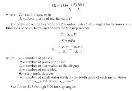
TABLE 5.13 Two-Pole Three-Phase Step Angles
| P = 2, m | = 3, Ssm = 6 | ||
| n | Ss | Sr | |
| 1 | 6 | 4 | 30.0000 |
| 1 | 6 | 8 | 15.0000 |
| 2 | 12 | 10 | 12.000 |
| 2 | 12 | 14 | 8.5714 |
| 3 | 18 | 16 | 7.5000 |
| 3 | 18 | 20 | 6.0000 |
| 4 | 24 | 22 | 5.4545 |
| 4 | 24 | 26 | 4.6154 |
| 5 | 30 | 28 | 4.2857 |
| 5 | 30 | 32 | 3.7500 |
| 6 | 36 | 34 | 3.5294 |
| 6 | 36 | 38 | 3.1579 |
| 7 | 42 | 40 | 3.0000 |
| 7 | 42 | 44 | 2.7273 |
| 8 | 48 | 46 | 2.6087 |
| 8 | 48 | 50 | 2.4000 |
| 9 | 54 | 52 | 2.3077 |
| 9 | 54 | 56 | 2.1429 |
| 10 | 60 | 58 | 2.0690 |
| 10 | 60 | 62 | 1.9355 |
TABLE 5.14 Two-Pole Four-Phase Step Angles
| P = 2, m | = 4, Ssm = 8 | ||
| n | Ss | Sr | |
| 1 | 8 | 6 | 15.0000 |
| 1 | 8 | 10 | 9.0000 |
| 2 | 16 | 14 | 6.4286 |
| 2 | 16 | 18 | 5.0000 |
| 3 | 24 | 22 | 4.0909 |
| 3 | 24 | 26 | 3.4615 |
| 4 | 32 | 30 | 3.0000 |
| 4 | 32 | 34 | 2.6471 |
| 5 | 40 | 38 | 2.3684 |
| 5 | 40 | 42 | 2.1429 |
| 6 | 48 | 46 | 1.9565 |
| 6 | 48 | 50 | 1.8000 |
| 7 | 56 | 54 | 1.6667 |
| 7 | 56 | 58 | 1.5517 |
| 8 | 64 | 62 | 1.4516 |
| 8 | 64 | 66 | 1.3636 |
| 9 | 72 | 70 | 1.2857 |
| 9 | 72 | 74 | 1.2162 |
| 10 | 80 | 78 | 1.1589 |
| 10 | 80 | 82 | 1.0976 |
TABLE 5.15 Four-Pole Three-Phase Step Angles
| P = 4, m = | 3, Ssm = 12 | ||
| n | Ss | Sr | |
| 1 | 12 | 8 | 15.0000 |
| 1 | 12 | 16 | 7.5000 |
| 2 | 24 | 20 | 6.0000 |
| 2 | 24 | 28 | 4.2857 |
| 3 | 36 | 32 | 3.7500 |
| 3 | 36 | 40 | 3.0000 |
| 4 | 48 | 44 | 2.7273 |
| 4 | 48 | 52 | 2.3077 |
| 5 | 60 | 56 | 2.1429 |
| 5 | 60 | 64 | 1.8750 |
| 6 | 72 | 68 | 1.7647 |
| 6 | 72 | 76 | 1.5789 |
| 7 | 84 | 80 | 1.5000 |
| 7 | 84 | 88 | 1.3636 |
| 8 | 96 | 92 | 1.3043 |
| 8 | 96 | 100 | 1.2000 |
TABLE 5.16 Four-Pole Four-Phase Step Angles
| P = 4, m | = 4, Ssm = 16 | ||
| n | Ss | Sr | |
| 1 | 16 | 12 | 7.5000 |
| 1 | 16 | 20 | 4.5000 |
| 2 | 32 | 28 | 3.2143 |
| 2 | 32 | 36 | 2.5000 |
| 3 | 48 | 44 | 2.0455 |
| 3 | 48 | 52 | 1.7308 |
| 4 | 64 | 60 | 1.5000 |
| 4 | 64 | 68 | 1.3235 |
| 5 | 80 | 76 | 1.1842 |
| 5 | 80 | 84 | 1.0714 |
| 6 | 96 | 92 | 0.9783 |
| 6 | 96 | 100 | 0.9000 |
| 7 | 112 | 108 | 0.8333 |
| 7 | 112 | 116 | 0.7759 |
| 8 | 128 | 124 | 0.7258 |
| 8 | 128 | 132 | 0.6818 |
TABLE 5.17 Six-Pole Step Angles
| P = 6, m = | 3, Ssm = 18 | ||
| n | Ss | Sr | |
| 1 | 18 | 12 | 10.0000 |
| 1 | 18 | 24 | 5.0000 |
| 2 | 36 | 30 | 4.0000 |
| 2 | 36 | 42 | 2.8571 |
| 3 | 54 | 48 | 2.5000 |
| 3 | 54 | 60 | 2.0000 |
| 4 | 72 | 66 | 1.8182 |
| 4 | 72 | 78 | 1.5385 |
| 5 | 90 | 84 | 1.4286 |
| 5 | 90 | 96 | 1.2500 |
| 6 | 108 | 102 | 1.1765 |
| 6 | 108 | 114 | 1.0526 |
Lamination Design.
After selecting the phases, poles, and teeth required for the motor, it is necessary to complete the stator and rotor lamination designs. For stators with one tooth per pole, use the following method for determining sizes, except be certain to leave a gap between poles at the stator ID large enough to insert the windings. If a needle winder is being used, this may be determined as follows:Wso = max wire OD + 0.010 in clearance for max wire + 0.025 in needle wall + 0.010 in clearance for needle movement + (2 x slot insulation thickness)
TABLE 5.18 Six-Pole Four-Phase Step Angles
| P = 6, m | = 4, Ssm = 24 | ||
| n | Ss | Sr | |
| 1 | 24 | 18 | 5.0000 |
| 1 | 24 | 30 | 3.0000 |
| 2 | 48 | 42 | 2.1429 |
| 2 | 48 | 54 | 1.6667 |
| 3 | 72 | 66 | 1.3636 |
| 3 | 72 | 78 | 1.1538 |
| 4 | 96 | 90 | 1.0000 |
| 4 | 96 | 102 | 0.8824 |
| 5 | 120 | 114 | 0.7895 |
| 5 | 120 | 126 | 0.7143 |
| 6 | 144 | 138 | 0.6522 |
| 6 | 144 | 150 | 0.6000 |
TABLE 5.19 Eight-Pole Three-Phase Step Angles
| P = 8, m | = 3, S sm = 24 | ||
| n | Ss | Sr | es |
| 1 | 24 | 16 | 7.5000 |
| 1 | 24 | 32 | 3.7500 |
| 2 | 48 | 40 | 3.0000 |
| 2 | 48 | 56 | 2.1429 |
| 3 | 72 | 64 | 1.8750 |
| 3 | 72 | 80 | 1.5000 |
| 4 | 96 | 88 | 1.3636 |
| 4 | 96 | 104 | 1.1538 |
TABLE 5.20 Eight-Pole Four-Phase Step Angles
| P = 8, m = | 4, Ssm = 32 | ||
| n | Ss | ||
| 1 | 32 | 24 | 3.7500 |
| 1 | 32 | 40 | 2.2500 |
| 2 | 64 | 56 | 1.6071 |
| 2 | 64 | 72 | 1.2500 |
| 3 | 96 | 88 | 1.0227 |
| 3 | 96 | 104 | 0.8654 |
| 4 | 128 | 120 | 0.7500 |
| 4 | 128 | 136 | 0.6618 |
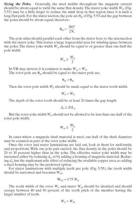
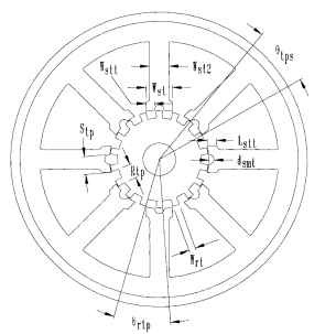
FIGURE 5.55 Cross section of 5° variable-reluctance step motor.
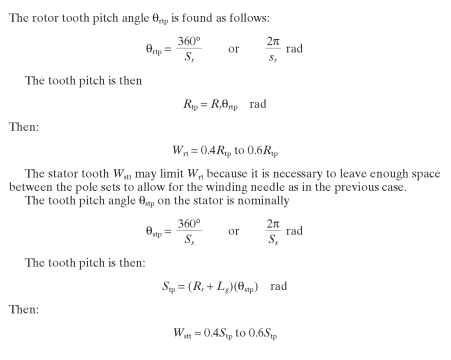
In the case of small motors, these dimensions are somewhat limited by mechanical considerations. The minimum width of any stamped part should be 1.5 times the material thickness.

It should be noted here that there are stator lamination designs that require a large number of teeth, but the size of the ID would make it impossible to have enough space between the poles to insert the winding needle. In these cases, the designer should eliminate some of the teeth but keep the original spacing. For example, the 1.8° step motor requires 48 stator teeth on 8 major stator teeth and 50 rotor teeth. Most motors of this step angle drop 1 minor tooth from each major tooth so that the stator actually has 40 stator teeth on a 48-tooth spacing.
Estimating Slot Area and Winding Space for Straight-Sided Teeth. Before a winding can be calculated, it is necessary to determine the available slot area. First, calculate the gross slot area (GSA), then subtract the insulation area, winding needle area, and slot wedge area (Fig. 5.56).
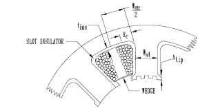
FIGURE 5.56 Stator slot.

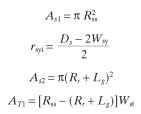
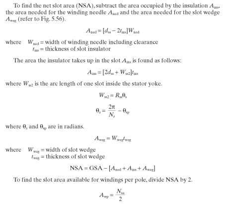
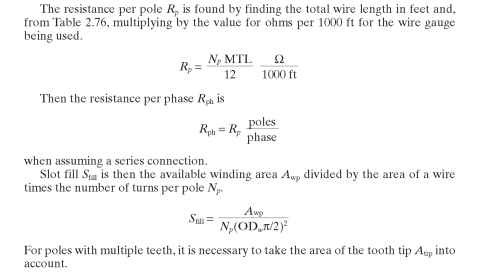
Calculating Resistance. To determine resistance the mean turn length (MTL), the number of turns, and the gauge of wire must be known.

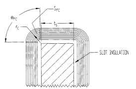
FIGURE 5.57 Side view of end turn.
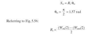
Estimating Rated Torque. A formula for predicting peak torque comes from Trickey. Here:
where P = poles per phase I = current per phase
The number of turns per pole Np can be estimated by determining the ampere-turns required to nearly saturate the steel chosen for the motor laminations, then selecting the wire size that will keep current densities reasonable. Stack length may have to be adjusted.Actual winding selection is heavily dependent on the drive type.
Once the number of turns has been calculated, determine the wire size that can be used.
Look up the wire sizes in Table 2.76. Then calculate the resistance per phase i?ph. Divide this value into Vs to determine the maximum current possible.
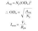
If this value times Np does not equal or exceed the required Npi, some adjustments will have to be made.
Verifying the Design. Note that up to this point, many assumptions have been made about flux densities, dimensions, and ampere-turns per pole. It is now time to select the materials and verify the reasonableness of the design.
Select the lamination steel by determining the importance of core loss in this application. If it is a high-speed, high-switching-frequency, or high-efficiency motor, start by selecting a medium-grade material such as M-19,29 gauge. If it is a very cost-sensitive application, try cold-rolled steel, 24 gauge. In military or space applications, 0.006-in vanadium permendur might be required.
The loose assumption made previously can obviously lead to a less-than-perfect design. The next step is to model the motor in a boundary element analysis (BEA) or finite element analysis (FEA) software package and more accurately calculate the flux and torque. These packages give only static performance, but the results can be utilized by the designer to more accurately predict dynamic performance.
Figures 5.58,5.59 and 5.60 show the effects of various rotor and stator materials on motor torque. Figure 5.58 shows an M-19 stator core with a cast-iron rotor, an M-19 rotor, and a cold-rolled steel (CRS) rotor. Note that the M-19 and CRS rotors have nearly identical torques, while the cast-iron rotor has much lower torques. In Fig. 5.59, the stator is made of cast iron. It has less torque than the M-19 stator with all three rotors, but the M-19 and CRS rotors provide more torque than the cast-iron rotor. Figure 5.60 shows the same plots except the stator is now CRS. The M-19 stator provides the best overall torque, notwithstanding the rotor material being M-19 or CRS. These curves do not take core loss into account. The M-19 material provides lower core loss.
Figures 5.58, 5.59, and 5.60 were derived from a BEA of a VR step motor with 2.5-in OD stator with Ns = 8 and Nr = 6. The torque was calculated for a 1.0-m stack length with 1 phase turned on. The net current for 1 coil side is 350 A for this analysis. Note the "xE1" on the torque scale to correctly read the torque values. The values of torque and rotation are negative because the software considers CCW rotation to be in the positive direction. To convert these torque values to the torque of an actual motor, multiply these values by 0.0254 x Lstk, where Lstk is in inches. Figure 5.61 shows a plot of flux linkage versus current of the motor with the rotor in the aligned and unaligned positions.
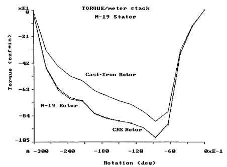
FIGURE 5.58 Torque versus rotation for M-19 stator with alternative rotor materials.
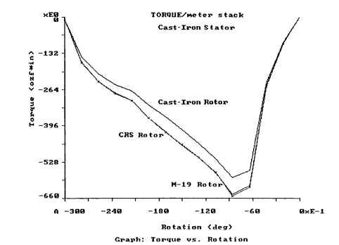
FIGURE 5.59 Torque versus rotation for cast-iron stator with various rotor materials.
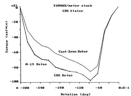
FIGURE 5.60 Torque versus rotation for CRS stator with various rotor materials.
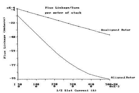
FIGURE 5.61 Flux linkage versus current.