A typical PM step motor is shown in Fig. 5.62 and was described earlier. Since this is a step motor, rotor inertia is an important item in the design. If a rotor or load inertia has been specified, this component should be designed first.
The rotor assembly (Fig. 5.63) consists of a steel shaft, an aluminum hub, and a cylindrical ring magnet. Since all components rotate about the same center, the individual inertias can be calculated and then added together to obtain the total inertia.
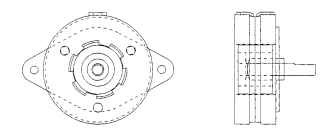
FIGURE 5.62 Permanent-magnet step motor.
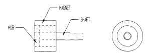
FIGURE 5.63 Permanent-magnet step-motor rotor assembly.

FIGURE 5.64 Permanent-magnet step-motor shaft.
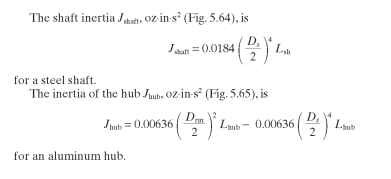
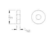
FIGURE 5.65 Permanent-magnet step-motor hub dimensions.
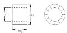
FIGURE 5.66 Permanent-magnet step-motor magnet dimensions.

TABLE 5.21 Densities of Common Magnetic Materials
| Material | lb/in3 | Density oz/in3 | g/cm3 |
| Bonded ferrite | 0.134 | 2.14 | 3.71 |
| Sintered ferrite | 0.177 | 2.83 | 4.90 |
| Alnico | 0.264 | 4.22 | 7.31 |
| Samarium cobalt | 0.302 | 4.83 | 8.35 |
| Neodymium-iron-boron | 0.271 | 4.34 | 7.50 |
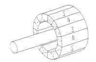
FIGURE 5.67 Permanent-magnet rotor magnetization pattern.

Air Gap. The air gap length Lg on these motors is much larger than on VR step motors. An Lg of 0.010 to 0.015 in per side is common.
Stator Pole Pieces. The ID of the stator Dsi is found as follows:
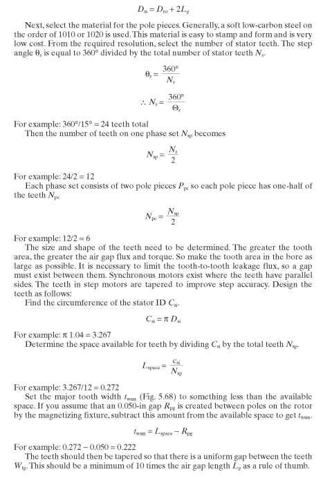
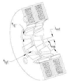
FIGURE 5.68 Stator of permanent-magnet step motor
The tooth tip cannot overlap the housing edge because it would create a magnetic short circuit. The reluctance of the path to the housing would be much lower than the path to the rotor. Sizing the dimension between the housing and the tooth tip Wtgt should follow a rule similar to the one for finding the distance between the teeth. Since the tooth is much narrower at the tip than at the base, the effect of leakage would be much less; so a rule of 5 times the air gap length is generally satisfactory.
The actual size and shape of the teeth depends on the motor length as well as the rotor diameter. The motor length is often limited by the application specification. The stator outside diameter Dso should be about twice the inside diameter of the stator.
The thickness of the material should be as thin as possible for ease of forming but not so thin as to be easily deformed in normal handling. Since these parts are in the main flux path, they should not be made so thin as to add significant reluctance to the circuit. A rule of thumb is to select a material in the range of 0.025 to 0.075 in as a place to start. Material in the range of 0.040- to 0.050-in CRS is a good choice.
When the pole pieces are assembled, the inside pieces Pc1 and Pc2 (Fig. 5.69) that are joined together require some kind of locating device. It is important that these pieces be offset from each other by one-half tooth pitch. The more accurate the alignment, the better the step accuracy will be. Pole pieces (Pc3 and Pc4) need to be accurately located one tooth pitch from their mating halves. Assembly of this unit is the key to its performance. Keep the parts symmetrical and uniform for best results.
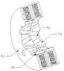
FIGURE 5.69 Permanent-magnet step-motor stator piece.
Windings. This motor supplies the drive mmf from coils wound on bobbins and inserted between pole pieces 1 and 3 and 2 and 4, respectively. The bobbin (Fig. 5.70) is usually made of a nylon material. The OD Dbso is slightly smaller than the stator OD.
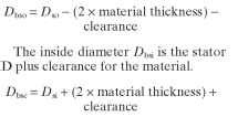
The bobbin should have a wall thickness in the range of 0.025 in. The bobbin width is a function of the motor length. The available winding area Awnd is
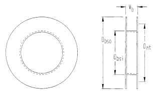
FIGURE 5.70 Permanent-magnet step-motor bobbin.
Winding Resistance. The resistance ,Rph is simply the mean turn length (MTL) times the number of turns VVph times the resistivity p of the wire gauge being used.
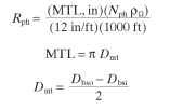
Estimating the Torque. The torque is a function of the air gap flux )s, the number of poles, and the stator ampere-turns. Kuo (1979) did an exhaustive treatise in which he determined that the average torque Tav,Nm, is
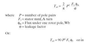
F1 is just the coil current times the number of turns in the coil.
Calculating o, Fi, and <) is difficult and time consuming. The permeances of the main flux paths and leakage flux paths must be determined. The load line on the magnet curve must be established. The mmf drops in the circuit must be calculated. Typically, the mmf drops do not equal the mmf supplied, so it is necessary to iterate to a solution. The following method may be used to estimate the air gap flux and torque. However very accurate predictions generally require the use of a three-dimensional boundary or finite element analysis.
• Find the permeance coefficient (Pc) of the magnet
• Determine the flux density in the magnet
• Find the total flux
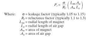
The area of the magnet is not necessarily the same as the area of the air gap, because motors typically have magnets somewhat shorter than the stator. Ag is usually larger than Am.
The permeance coefficient determines the load line of the magnet on its normal demagnetization curve. These curves are commonly supplied by the magnet manufacturer. A typical curve is shown in Fig. 5.71 and is the upper-left quadrant of the hysteresis loop shown in other sections of this handtopic.
To plot the load line, take the arctangent of the permeance coefficient, calculate the angle \|/ = tan-1 Pc, and plot the line as shown in Fig. 5.71.The flux density in the magnet Bm can be found by finding the intersection of the load line and the normal curve and reading the induction from the right vertical axis. The flux in the magnet is found by multiplying the flux density by the area of the magnet Am cm2:
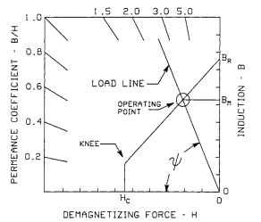
FIGURE 5.71 Magnetic load line and operating point.
Then: