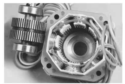
The hybrid step motor is generally constructed as shown in Fig. 5.50. It has a stator assembly similar to that of the VR motor, but the rotor consists of three sections. Two pieces are similar to the VR step-motor rotor, but a magnet is placed between them, and they are offset circumferentially from each other by one-half tooth pitch.

FIGURE 5.50 Hybrid step motor.
This motor is termed a hybrid because it uses elements of both variable-reluctance and permanent-magnet-rotor step motors. The commonly known version is the 1.8° step-angle motor. It was originally designed as an ac two-phase synchronous inductor motor for low-speed applications.
Its stator construction is similar to that of a variable-reluctance step motor with salient poles (multiple teeth per pole). The phase windings may be either monofilar or bifilar coils, as discussed for the stamped-construction motor. The rotor contains a cylindrical permanent magnet axially magnetized and enclosed on each end by a soft-iron cup with uniformly spaced teeth. As for the variable-reluctance motor, the number of stator phases and differing number of stator and rotor teeth determine the step angle.
Motor Operation. When a stator phase consisting of two or more poles is energized, the teeth in each rotor half align themselves with the nearest unlike stator
teeth on the energized poles. A flux path exists from the stator pole rotor half, axi-ally through the rotor, back to a different stator pole, and through the back iron. A new position of rotor alignment is produced each time one phase is deenergized and the next is energized in the same type of sequence as described for the stamped-construction motor. Similar operation is obtained when multiple motor phases are energized.
The permanent-magnet rotor provides the hybrid step motor with good damping characteristics. The hybrid motor has a higher torque per input watt ratio than the stamped construction motor, and it exhibits better step-angle accuracy. Typical step-angle values lie in the range of 0.9° to 3.6°.