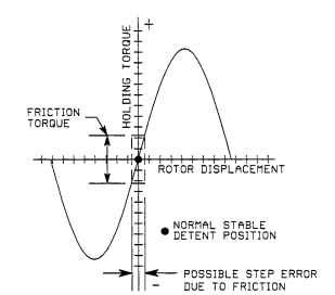
If a step motor is turned on and the rotor is mechanically rotated, a holding-torque curve such as the one shown in Fig. 5.51 will be produced.The torque will go positive and negative as it moves through its detent position. Figure 5.51 shows a possible step error caused by motor friction and magnetic structure inaccuracy.

FIGURE 5.51 Holding torque curve.
If phase A is turned on and plotted for several cycles, and then B and C are alternately plotted from the same starting position, the curve in Fig. 5.52 is produced. The maximum available running torque is at the points where the curves produced by the alternate phases intersect.