5.2.9
This subsection discusses the most common step-motor characteristics and methods of determining them.
Resistance. Resistance is measured using a Wheatstone bridge or equivalent.
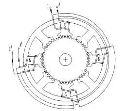
FIGURE 5.80 4-phase variable-reluctance step motor winding connections. Polarity as shown with current in A; current reverses with polarity in C.
Phase Inductance. The inductance of each phase winding is measured using an impedance bridge capable of generating a 1000-Hz ac voltage signal. The rotor position must be in the null or rotor-stator tooth-aligned position. The VR step motor may require a dc voltage signal as well to ensure proper alignment. Other methods may be used, but the values may differ and the method should be identified.
Holding or Static Torque. Apply rated dc current to one or two phases of the motor using a suitable torque measuring device, such as a dynamometer or torque watch. Determine the amount of torque required to cause slow rotation of the shaft. A typical curve is shown in Fig. 5.81.
As subsequent phases are plotted relative to each other, the complete torque profile as shown in Fig. 5.82 is produced. The intersection of the torque curves is the maximum continuous torque that can be expected.
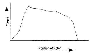
FIGURE 5.81 Torque versus rotor position: one phase on.
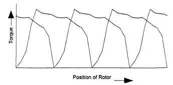
FIGURE 5.82 Torque versus rotor position: four phases on.
Pull-In Torque. A particular step rate is selected but is not yet gated to the step-motor drive circuit, and the brake is then energized. The step pulses are then gated to the step motor, and the motor attempts to accelerate itself and the torque transducer and brake into a synchronous speed.
As it succeeds, a larger brake torque is required. If the step motor fails to accelerate, the step pulses are turned off. The brake torque is reduced slightly, and the pulses are again gated to the stepping motor. This process is repeated until the stepping motor is just able to gain synchronism at the set brake torque. The torque is measured after the motor and test setup have reached synchronous speed.
Pull-Out Torque. Set the brake torque to a minimum load and ramp the step motor up to some specified step rate. The brake torque is slowly increased until the stepping motor loses synchronism. The torque is measured just before the motor loses synchronism. Record the minimum and maximum torques. Use the average value to generate the pull-out-torque curve. This test is repeated at different step rates until sufficient data has been recorded to plot the pull-out curve.
In the running mode with a constant voltage supply of increasing frequency, the motor accelerates with decreasing torque (Fig. 5.83). The speed-torque curve resembles that of a universal motor. In this case, the torque decreases because the inductance limits the winding current as the switching frequency increases. Core losses are also increased as frequency increases. Employing a control system that overcomes the inductance and increases coil current at high speeds will significantly improve the output torque.
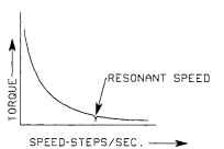
FIGURE 5.83 Speed-torque curve of step motor.
Inertia. Rotor inertia may be determined by removing the rotor and suspending it from a thin steel rod having a known torsion constant c. Displace the rotor slightly and time the period of oscillation f. The moment of inertia J is calculated from J = (C/4)2 f2.
Note: Most manufacturers publish this data. There are also test devices available that give a direct readout of inertia.
Residual or Detent Torque. With no power applied and leads separated (not touching), use a suitable measuring device to determine the torque required to cause slow rotation.
Step Accuracy. Accuracy from step to step measured in degrees of arc can be determined using an encoder having at least 10 times the resolution of the error to be measured. The encoder output is compared with the theoretical individual step angle to determine noncumulative error plus or minus, step to step.
Step accuracy is affected by part and assembly tolerances, friction, and magnetic balance. The tighter the tolerance, the better the step accuracy. The lower the friction, the better the step accuracy. The better the magnetic-circuit balance, the better the step accuracy.
Counter-EMF (PM Step Motors). The step-motor counter-emf can be determined by driving the rotor at a constant known speed with the stator winding deenergized and open circuited. A periodic voltage will be generated in the stator windings whose magnitude is proportional to speed and is generally sinusoidal. The average value of the voltage Eg divided by rotor speed co equals the counter-emf constant.
Friction. There are two components of friction, static friction Ts and coulomb friction Tf. Friction may be measured using a rotary torque transducer and a dc servo/tachometer. Ts is the torque required to start rotation. Tf is the torque required to drive the step motor as speed varies after rotation starts.
Damping. The friction and windage torque Tf and Tw can be determined by plot-

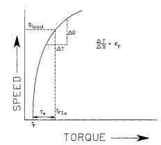
FIGURE 5.84 Kf curve for step motor.
Torque Constant. To obtain the torque versus current plot necessary to calculate the torque constant Kt, position the rotor at the maximum torque angle point. Increase the winding current and measure torque and current until the stator is driven into magnetic saturation. Plot the data and calculate Kt = peak torque, (ozin)/(winding current,A).
Natural Frequency w0. This is the frequency at which the rotor will oscillate freely. It is a function of the torque, the pole pairs, and the inertia of the motor.
Where: T = torque, ozin
P = number of pole pairs Jr = rotor inertia, ozins2
The motor will oscillate and lose synchronism at this frequency or a harmonic of this frequency.
Resonance. A phenomenon known as midfrequency resonance occurs in step motors operated in the open-loop mode. When this frequency range is reached, the motor develops velocity perturbations about the nominal drive velocity which reach catastrophic proportions, resulting in the loss of synchronism. The motor stalls as a result. If proper damping is used, it is possible to get through this region and operate above the resonant point.
Damping. This is the process of adding retarding torque to the motor system such that velocity perturbations are restrained. This can be done by adding friction or, electronically, by applying current to a previous phase.