A typical hybrid step motor is illustrated in Fig. 5.72.
The method for designing this motor is the same as that for the VR step motor. The major difference is that the rotor (Fig. 5.73) has two pieces that are hobbed, extruded, or punched as laminations. These pieces are partially hollowed out (Fig. 5.74) and partially enclose a cylindrical magnet (Fig. 5.75). When these parts are built into a rotor and shaft assembly (Fig. 5.76), the two end pieces are offset from each other by one-half tooth pitch circumferentially.
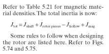
The rotor inertia calculation now changes somewhat. Follow the method outlined in the VR step-motor section, except subtract out the hollow portion of the end pieces and add in the magnet inertia. The inertia of the hollowed portion is

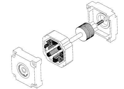
FIGURE 5.72 Hybrid step-motor construction.
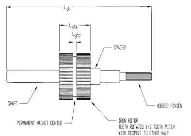
FIGURE 5.73 Hybrid rotor construction.
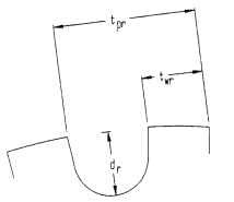
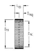
FIGURE 5.74 Iron rotor pole piece.
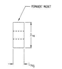
FIGURE 5.75 Permanent magnet.
Select a magnet material that will provide the needed flux and has the necessary demagnetization characteristics. Alnico is a common magnet material for these rotors; however, rare earth materials are used often because of their high resistance to demagnetization.


Hybrid Motor Torque. According to Kuo (1979) the torque consists of three components which include the mutual torque Tm, the variable reluctance torque Tvr, and the detent torque TD.
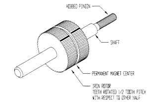
FIGURE 5.76 Hybrid motor with half tooth pitch offset.
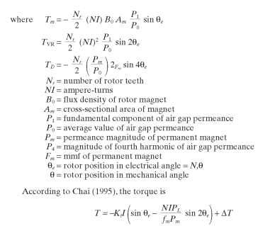
These methods take into account the harmonic torques and require complex models for accurate results. As an initial try, the method used for the PM step motor will get you into the ballpark. For accurate prediction of torque, the VR motor should be modeled on a two-dimensional BEA or FEA software package. The PM and hybrid motors should be modeled on a three-dimensional BEA or FEA package.
Windings. PM step motors are simply wound on bobbins with one (monofilar) or two (bifilar) strands of wire per bobbin. They are then connected to operate as follows. The monofilar windings are operated on a bipolar driver. The bifilar windings are operated on a unipolar driver. The bipolar driver allows for greater copper utilization than the unipolar driver because only half the copper is being used at any one time in the unipolar system.
Hybrid and VR step motors may utilize a variety of winding schemes to obtain varying results. Some of the common connections are listed here.
^ Figure 5.77 shows a VR three-phase step motor with the windings connected to produce an S-N pole arrangement for one-phase-on operation. Here the flux divides and goes around the complete stator yoke.
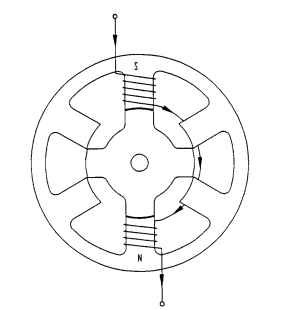
FIGURE 5.77 6/4 3-phase variable-reluctance step motor.
^ Figure 5.78 shows a connection for two-phase-on operation of a four-phase motor. This motor has long flux paths, similar to the one-phase-on motor.
• Figure 5.79 shows another two-phase-on motor, except that the windings are connected to provide short flux paths. Here the flux exits the north pole and goes through the rotor to an adjacent south pole. This reduces the stator yoke mmf drop and core losses, making for a more efficient motor.
^ Figure 5.80 shows a four-phase motor wound with a bifilar winding to allow for unipolar operation.
These winding configurations all have peculiar characteristics along with advantages and disadvantages and should be selected based on the system requirements.
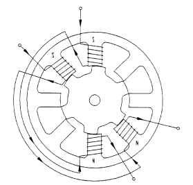
FIGURE 5.78 2-phase-on 4-phase step motor with long flux paths.
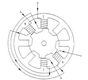
FIGURE 5.79 2-phase-on 4-phase step motor with short flux paths.