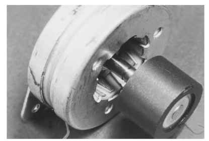
The PM step motor is illustrated in Fig. 5.47. It consists of two sets of stamped steel cups with diagonal teeth facing the rotor. Each set of cups circumscribes a coil of wire. The two sets are positioned with respect to each other such that they circumscribe the rotor but they are offset from each other by one-half of a tooth pitch.

FIGURE 5.47 Permanent-magnet step motor.
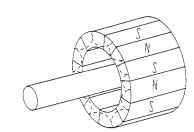
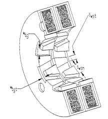
The permanent-magnet-rotor step motor is commonly referred to as the stamped-construction or sheet-metal step motor. It is sometimes called simply a PM step motor but should not be confused with the hybrid permanent-magnet step motor. The rotor in a stamped-construction motor is a smooth cylindrical permanent magnet radially magnetized with alternating N and S poles (Fig. 5.48).The stator has two cup-shaped halves with formed stator teeth (Fig. 5.49). Each half contains a circular, bobbin-wound coil. Because of this simple design, the price is low, but step accuracy and speed may not equal the performance of other step-motor types.

FIGURE 5.48 Magnetization pattern of permanent-magnet step-motor rotor.

FIGURE 5.49 Cutaway view of permanent-magnet step-motor stator.
Stamped-construction motors are produced with two types of coil windings which require different types of drive circuits:
• Bipolar (monofilar)—a single winding per bobbin. Motor operation requires a drive circuit which can reverse the direction of current in the winding. Either a bridge inverter or a circuit with positive and negative supplies may be used.
• Unipolar (bifilar)—two windings per bobbin. Motor operation requires a drive circuit which energizes only one of the two windings at a time. In addition, the direction of current flow in each winding is such that fluxes of opposite polarity are produced. Frequently, the two windings are connected inside the motor to form the equivalent of a single center-tapped winding. Only one power supply and two switches per bobbin are sufficient to operate a motor with this type of winding.
Motor Operation. The individual sta-tor halves have uniformly spaced teeth. The two halves are offset by one-half of a tooth pitch. The rotor contains the same number of teeth as each stator half. When one stator half is energized, the rotor aligns its poles with the stator teeth of opposite polarity. A flux path exists from stator tooth to opposite rotor pole, between adjacent rotor poles, back to the
opposite (adjacent) stator tooth, and through the stator back iron. When the energization is switched from one stator half to the other, the rotor moves to a new position of alignment one-fourth of a pole pitch from the previous position. The next step occurs when the original stator half is energized with opposite polarity. A four-step switching sequence produces a movement of one pole pitch.The same motion may be achieved by energizing both stator halves at once and allowing the rotor to align itself with the resultant magnetic field. Typical motors of this type have either 12 or 24 poles per stator half, and thus produce step angles of 15° or 7.5°, respectively.
The presence of the permanent-magnet rotor results in a lower operating power requirement than that of the VR motor. It also contributes to good damping (settling) characteristics because of the unenergized detent torque. This type of construction is not suitable for small step angles.