Stator and coil assemblies for induction motors usually have distributed wound cores. The objective here is to produce a sinusoidal air gap mmf. A coil of wire, as shown in Fig. 6.4, produces a square-wave mmf. A distributed winding improves this condition.
Next is an example of how sinusoidal distribution is determined. This is followed by tables showing near-sinusoidal winding distributions for some common pole-tooth combinations.
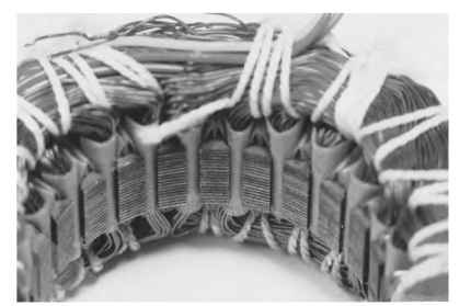
FIGURE 6.2 Stator and coil assembly lead end.
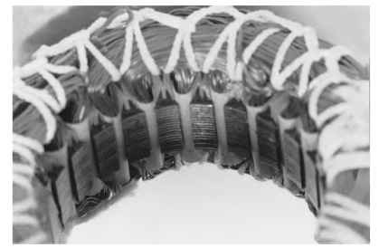
FIGURE 6.3 Stator and coil assembly opposite lead end.
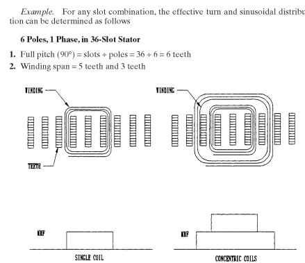
FIGURE 6.4 Air gap mmf waves versus winding distribution.
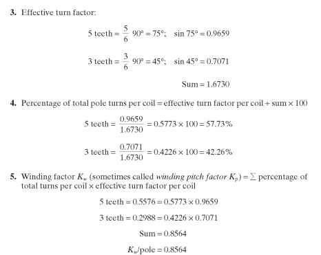
Tables 6.1 and 6.2 show sinusoidal winding distributions for even and odd slot combinations, respectively.
Polyphase motors can be wound in a lap winding configuration (Fig. 6.5) or a concentrically distributed winding configuration (Fig. 6.6). Single-phase motors are typically wound and inserted in the manner shown in Fig. 6.7. Figure 6.8 shows a typical
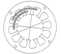
FIGURE 6.5 Lap-wound polyphase configuration.
TABLE 6.1 Sinusoidal Winding Distribution—Even Tooth Spans
| Slots per | Tooth | span | ||||||||
| pole | 2 | 4 | 6 | 8 | 10 | 12 | 14 | 16 | 18 | |
| 18 | 6.3 | 9.0 | 11.6 | 13.8 | 15.7 | 17.0 | 17.8 | 9.0 | 0.808 | |
| 9.6 | 12.4 | 14.7 | 16.7 | 18.1 | 18.9 | 9.6 | 0.835 | |||
| 13.7 | 16.4 | 18.4 | 20.0 | 20.9 | 10.6 | 0.873 | ||||
| 18.9 | 21.3 26.3 | 23.2 28.6 | 24.3 29.9 | 12.3 15.2 | 0.909 0.944 | |||||
| 16 | 7.9 | 11.3 | 14.4 | 17.2 | 18.9 | 20.0 | 10.3 | 0.812 | ||
| 12.4 | 15.7 | 18.5 | 20.5 | 21.8 | 11.1 | 0.848 | ||||
| 17.9 | 21.1 25.7 | 23.4 28.5 38.4 | 24.9 30.3 40.8 | 12.7 15.5 20.8 | 0.889 0.928 0.963 | |||||
| 12 | 6.8 | 13.2 | 18.6 | 22.8 | 25.4 | 13.2 | 0.789 | |||
| 14.1 | 20.0 23.3 | 24.5 28.5 37.2 | 27.3 31.8 41.4 65.9 | 14.1 16.4 21.4 34.1 | 0.829 0.883 0.936 0.977 | |||||
| 9 | 12.1 | 22.7 25.7 | 30.6 34.8 47.8 | 34.6 39.5 52.2 | 0.795 0.855 0.929 | |||||
| 8 | 15.3 | 28.0 33.1 | 36.8 43.4 64.8 | 19.9 23.5 35.2 | 0.795 0.870 0.950 | |||||
| 6 | 26.8 | 46.4 63.4 | 26.8 36.6 | 0.804 0.914 | ||||||
| 4 | 60.8 | 39.2 | 0.822 1.000 |