Consider an orthogonal two-winding unbalanced winding stator. The windings, in terms of a single-phase motor, would be the starting and running windings. These windings are unsymmetrical but have sinusoidally distributed stator coils. Figure 6.12 is representative of this motor. The two rotor windings are the same (symmetrical).
Applying Kirchhoff's voltage law to the four windings in Fig. 6.12 yields the following:
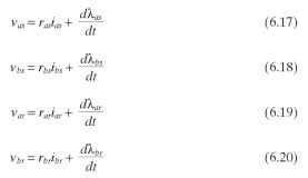
where rar = rbr
X = total flux linkage between stator and rotor windings
Now, if we are considering a typical two-winding single-phase motor, the rotor will be a round squirrel cage, giving a uniform air gap. If we assume that the magnetic circuit of the motor is magnetically linear, which approaches linearity if the magnetic-circuit permeance is large, then all the distribution of ampere-turns will appear across the air gaps (two air gaps per winding).
The flux linkage equations required to solve the previous voltage equations are the following:
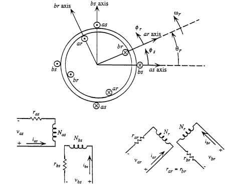
FIGURE 6.12 Orthogonal unbalanced two-winding stator.

The notation used here means, for example, Mbsar is the mutual inductance relative to the b winding of the stator when the a winding of the rotor is energized. In these equations, L is the self-inductance and M is the mutual inductance between the respective windings. Because of the orthogonality of the windings and also the squirrel-cage rotor, there are mutual inductance terms in the flux linkage equations in both stator and rotor which are zero.
and

Therefore, there are only three terms on the right side of Eqs. (6.21) to (6.24) for each of the four equations. Now it should be apparent that the mutual inductances
between the rotor and stator windings are functions of rotor position Qr. With sinu-soidally distributed windings, we are able to express these inductances for the assumed stator and rotor winding currents as follows:
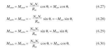
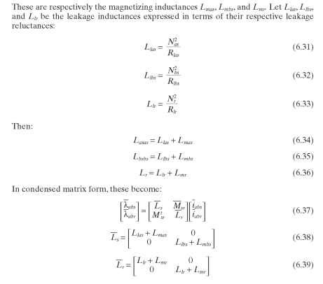
Rm is the reluctance of the air gaps for a sinusoidal distribution of flux in the air gap. Nas and Nbs are the effective turns of the stator windings, and Nr is the effective turns of the two rotor windings. The self-inductances of the stator and rotor can be expressed with leakage inductances included as follows:

Keep in mind that our goal is to develop the equivalent steady-state circuit for the single-phase motor; however, in this process we will also have available the dif-
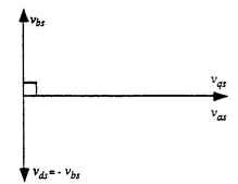
FIGURE 6.13 Stator transformation to q-d axis. The subscripts q and d represent the new voltage variables.
ferential equations to obtain the transient response. Our first step will be to remove the dependency of the mutual inductances [Eq. (6.10)] on rotor position. We will make an orthogonal q-d transformation to perform this step. The new set of variables will transform both stator and rotor machine parameters to a stationary axis q-d with the q axis aligned with the mmfa axis of the stator. This is the simplest of other available transformations which could also be used. Consider Fig. 6.13 for the stator transformation. The stator transformation is given for the stator voltages in terms of the new set of axis q-d. This transformation is indicated for voltage, but it could also represent currents and
flux linkages in the two stator windings. This transformation for the voltages is

The subscript s here represents stator.
To simplify the matrix notation, this can be written as follows:
where

Note that in Fig. 6.13 the stationary axis q is in the same direction as the assumed positive direction of mmfa whereas the assumed positive direction of the d axis is the negative of the positive direction of the mmfb axis. Note that the q-d axis is orthogonal and also note that

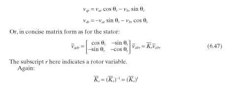
And we have represented voltages, but this could represent currents or flux linkages.