INTRODUCTION
During the past several decades, a number of attempts have been made to contain oil slicks (or any surface contaminants) in the open sea by means of a floating barrier. Many of those attempts were not very successful especially in the presence of waves and currents. The relative capabilities of these booms have not been properly quantified for lack of standard analysis or testing procedure (Hudon, 1992). In this regard, more analysis and experimental programs to identify important boom effectiveness parameters are needed.
To achieve the desirable performance of floating booms in the open sea, it is necessary to investigate the static and dynamic responses of individual boom sections under the action of waves; this kind of test is usually carried out in a wave flume, where open sea conditions can be reproduced at a scale.
Traditional methods use capacitance or conductivity gauges (Hughes, 1993) to measure the waves. One of these gauges only provides the measurement at one point; further, it isn't able to detect the interphase between two or more fluids, such as water and a hydrocarbon. An additional drawback of conventional wave gauges is their cost.
Other experiments such as velocity measurements, sand concentration measurements, bed level measurements, breakwater's behaviour, etc... and the set of traditional methods or instruments used in those experiments which goes from EMF, ADV for velocity measurements to pressure sensors, capacity wires, acoustic sensors, echo soundings for measuring wave height and sand concentration, are common used in wave flume experiments. All instruments have an associate error (Van Rijn, Grasmeijer & Ruessink, 2000), and an associate cost (most of them are too expensive for a lot of laboratories that can not afford pay those amount of money), certain limitations and some of them need a large term of calibration.
This paper presents another possibility for wave flume experiments, computer vision, which used a cheap and affordable technology (common video cameras and pc's), it is calibrated automatically (once we have developed the calibration task), is a non-intrusive technology and its potential uses could takes up all kind experiments developed in wave flumes. Are artificial vision's programmers who can give computer vision systems all possibilities inside the visual field of a video camera. Most experiments conducted in wave flumes and new ones can be carried out programming computer vision systems. In fact, in this paper, a new kind of wave flume experiment is presented, a kind of experiment that without artificial vision technology it couldn't be done.
BACKGROUND
Wave flume experiments are highly sensitive to whatever perturbation; therefore, the use of non-invasive measurement methodologies is mandatory if meaningful measures are desired. In fact, theoretical and experimental efforts whose results have been proposed in the literature have been mainly conducted focusing on the equilibrium conditions of the system (Niederoda and Dalton, 1982), (Kawata and Tsuchiya, 1988).
In contrast with most traditional methods used in wave flume experiments computer vision systems are non-invasive ones since the camera is situated outside the tank and in addition provide better accuracy than most traditional instruments.
The present work is part of a European Commission research project, "Advanced tools to protect the Gali-cian and Northern Portuguese coast against oil spills at sea", in which a number of measurements in a wave flume must be conducted, such as the instantaneous position of the water surface or the motions (Milgran, 1971) of a floating containment boom to achieve these objectives, a non-intrusive method is necessary (due to the presence of objects inside the tank) and the method has to be able to differentiate between at least two different fluids, with the oil slick in view.
Others works using image analysis to measure surface wave profile, have been developed over the past ten years (e.g., Erikson and Hanson, 2005; Garcia, Her-ranz, Negro, Varela & Flores, 2003; Javidi and Psaltis, 1999; Bonmarin, Rochefort & Bourguel, 1989; Zhang, 1996), but they were developed neither with a realtime approach nor as non-intrusive methods. In some of these techniques it is necessary to colour the water with a fluorescent dye (Erikson and Hanson, 2005), which is not convenient in most cases, and especially when two fluids must be used (Flores, Andreatta, Llona & Saavedra, 1998).
A FRAMEWORK FOR MEASURING WAVES LEVEL IN A WAVE FLUME WITH ARTIFICIAL VISION TECHNIQUES
Following is presented an artificial vision system which obtains the free surface position in all points of the image, from which the wave heights can be computed. For this aim we have to record a wave tank (see laboratory set-up in section 2) while it is generating waves and currents (a scale work frame), and after that we have to use the frames which make up the image to obtain the crest of the water (using computer vision techniques described in section 3) and translate the distances in the image to real distances (taking into account image rectification, see section 1).
Image Rectification
Lens distortion is an optical error in the lens that causes differences in magnification of the object at different points on the image; straight lines in the real world may appear curved on the image plane (Tsai, 1987). Since each lens element is radially symmetric, and the elements are typically placed with high precision on the same optical axis, this distortion is almost always radially symmetric and is referred to as radial lens distortion (Ojanen, 1999). There are two kinds of lens distortion: barrel distortion and pincushion distortion. Most lenses exhibit both properties at different scales.
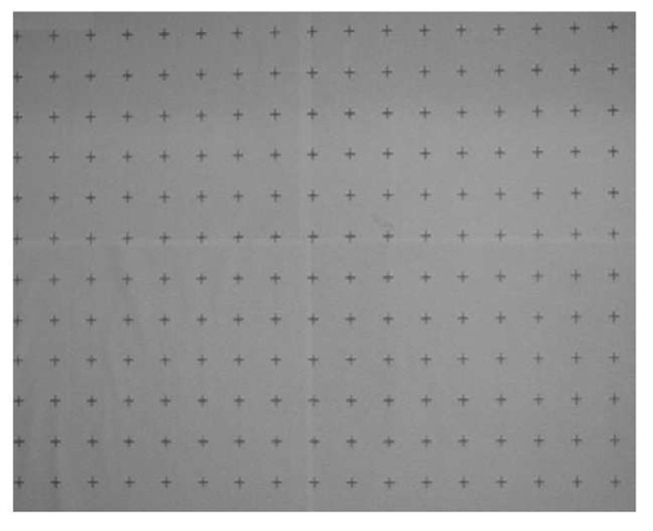
Figure 1. Template to image rectification. Crosses are equidistant with a 4cm separation.
To avoid lens distortion error and to provide a tool for transforming image distances (number of pixels) to real distances (mm) it is necessary to follow a rectification procedure.
Most image rectification procedures involve a two step process (Ojanen, 1991). (Holland, Holman & Sal-lenger, 1991): calibration of intrinsic camera parameters, and correction for a camera's extrinsic parameters (i.e., the location and rotation in space).
However, in our case we are only interested in transforming pixel measurements into real distances (mm). Transforming points from a real world surface to a non-coplanar image plane would imply an operator which, when applied to all frames, would considerably slow down the total process, which is not appropriate for our real-time approach.
So a .NET routine was developed to create a map with the corresponding factor (between pixel and real distances) for each group of pixels (four nearest control points on the target). Inputs to the model are a photographed image of the target sheet (see fig.1), and target dimensions (spacing between control points in the x- and y-directions).
Laboratory Set-Up and Procedure
The experiment was conduced in a 17.29-m long wave flume at the Centre of Technological Innovation in
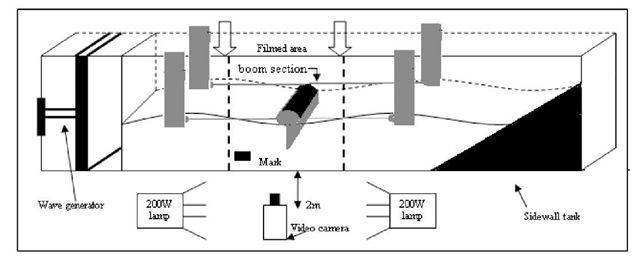
Figure 2. Laboratory set-up diagram
Construction and Civil Engineering (CITEEC), in the University of A Coruna, Spain. The flume section is 77 cm (height) x 59.6 cm (width). Wave generation is conducted by means of a piston-type paddle. A wave absorber is located near its end wall to prevent wave reflection. It consists of a perforated plate with a length of 3.04 m, which can be placed at different slopes. The experimental set-up is shown in fig. 2.
With the aim of validating the system, solitary waves were generated and measured on the base of images recorded by a video camera mounted laterally, which captured a flume length of 1 m. The waves were also measured with one conductivity wave gauge located within the flume area recorded by the video camera. These gauges provide an accuracy of ± 1 mm at a maximum sampling frequency of 30 Hz.
A video camera, Sony DCR-HC35E, was used in turn to record the waves; it worked on the PAL Western Europe standard, with a resolution of720 x 576 pixels, recording 25 frames per second.
The camera was mounted on a standard tripod and positioned approximately 2 m from the sidewall of the tank (see fig. 2). It remained fixed throughout the duration of a test. The procedure is as follows:
• Place one mark on the glass sidewall of the flume, on the bottom of the filmed area (see fig. 2);
• Place a template with equidistant marks (crosses) in a vertical plane parallel to the flume sidewall (see fig 1).
• Position the camera at a distance from the target plane (i.e., tank sidewall) depending on desired resolution.
• Adjust the camera taking into account the template's marks.
• Provide uniform and frontal lighting for the template.
• Film the template.
• Provide uniform lighting on the target plane and a uniformly colored background on the opposite sidewall (to block any unwanted objects from the field of view);
• Start filming.
The mark was placed horizontally on the glass sidewall of the flume, on the bottom of the filmed area in order to know a real distance between the bed of the tank and this mark, to avoid filming the bed of the tank and thus to film a smaller area (leading to a better resolution).
With regard to the lighting of the laboratory it is necessary to avoid direct lighting and consequently we can work without gleam and glints.
To achieve this kind of lighting, all lights in the laboratory were turned off and two halogen lamps of 200W were placed on both sides of the filmed area, one in front the other (see fig. 2).
Video Image Post-Processing
Image capture was carried out on a PC, Pentium 4, 3.00 GHz and 1.00 GB de RAM memory with the Windows XP platform. Filmed with the Sony DCR-HC35E1, a high-speed interface card, IEEE 1394 FireWireTM, was used to transfer digital data from the camcorder to the computer, and the still images were kept in the uncompressed bitmap format so that information would not be lost. De-interlacing was not necessary because of the quality of the obtained images and everything was done on a real-time approach.
An automatic tool for measuring waves from consecutive images was developed. The tool was developed under .NET framework, using C++ language and Open CV (Open Source Computer Vision Library, developed by Intel2) library. The computer vision procedure is as follows:
• Extract a frame from the video.
• Using different computer vision algorithms get the constant "pixel to mm" for each pixel.
• Using different computer vision algorithms, the crest of the wave is obtained.
• Work out the corresponding height, for all the pixels in the crest of the wave.
• Supply results.
• Repeat the process until the video finish.
With regard to get the constant "pixel to mm", a template with equidistant marks (crosses) is placed right up the glass sidewall of the tank and is filmed. Then a C++ routine recognize de centre of the crosses.
Results
A comparison of data extracted from video images with data measured by conventional instruments was done. The comparisons are not necessarily meant to validate the procedure as there are inherent errors with conventional instruments, as well; rather, the comparisons aim to justify the use of video images as an alternative method for measuring wave and profile change data.
Different isolated measurements with conductivity gauge were done at the same time the video camera was recording. Then results from both methods were compared.
The process followed to measure with conductivity gauge and the artificial vision system at the same time involves recognizing one point in x-axis (in the record video) where the gauge is situated (one color mark was pasted around the gauge to make easier this task) and after knowing the measure point of the gauge we create a file with the height of the wave in this x point for each image in the video. While the video-camera is recording one file with gauge measure is created. Once we have both measure files we have two determine manually the same time point in both files (due to the difficulty to initialize both systems at the same time). Now, we can compare both measurements.
A lot of tests were done with different wave parameters for wave period, wave height and using regular (sine form) and irregular waves. Test with waves between 40mm and 200mm of height were done.
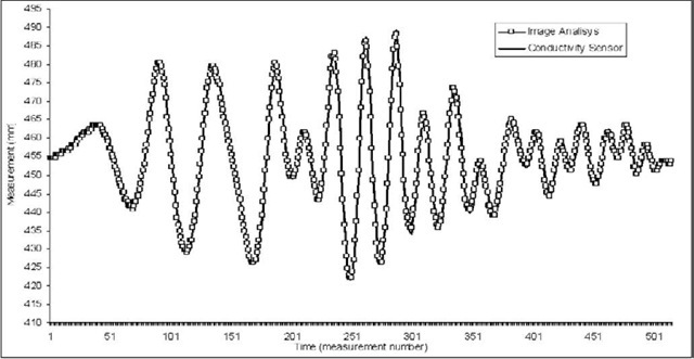
Using the camera DCR-HC35E, figure 3 shows one example of a test done, where the used wave was an irregular one, with a maximum period of 1s and a maximum value for wave amplitude of 70mm, excellent results were obtained as it can be seen in figure 4, where both measurements (conductivity sensor and video analysis) are quite similar.
Figure 3. Temporal sequence of measurement by sensor and image analysis
The correlation between sensor and video image analysis measurements has an associated mean square error of 0.9948.
In spite of these sources of error, after several tests, the average error between conductivity sensor measurements and video analysis is 0.8 mm with camera DCR-HC35E, a lot better compared with the 5 mm average error obtained in the best work done until this moment (Erikson and Hanson, 2005). But it isn't an indicative error because of the commented source of errors taken into account in this study, however the estimated real error from this video analysis system is 1 mm, that is to say, the equivalence between one pixel and a real distance, and in our case (with the commented video camera and distance from the tank) one pixel is equivalent to nearly 1mm. This error could be improvable with a camera which allows a better resolution or focusing a smaller area.
FUTURE TRENDS
This is the first part of a bigger system which is capable of measuring the motions of a containment boom section in the vertical axis and its slope angle (Kim, Muralid-haran, Kee, Jonson, & Seymour, 1998). Furthermore the system would be capable of making a distinction between the water and a contaminant, and thus would identify the area occupied by each fluid.
Another challenge is to test this system in other work spaces with different light conditions (i.e., in a different wave flume).
CONCLUSION
An artificial vision system was developed for these targets because these systems are non-intrusive and can separate a lot of different objects or fluids (anything that a human eye can differentiate) in the image and a non-intrusive method is necessary.
Other interesting aspects that these systems provide are:
• Cheaper price than traditional systems of measurement.
• Easier and faster to calibrate.
• It is unnecessary to mount an infrastructure to know what happens at different points of the tank (only one camera instead of an array of sensors).
• As the system is a non-intrusive one, it doesn't distort the experiments and their measurements.
• Provide high accuracy.
• Finally, this system is an innovation idea of applying computer vision techniques to civil engineering area and specifically in ports and coasts field. No similar works have been developed.
KEY TERMS
Color Spaces: (Konstantinos & Anastasios, 2000) supply a method to specify, sort and handle colors. These representations match n-dimensional sorts of the color feelings (n-components vector). Colors are represented by means of points in these spaces. There are lots of colors spaces and all of them start from the same concept, the Tri-chromatic theory of primary colors, red, green and blue.
Dilation: The dilation of an image by a structuring element 'Y' is defined as the maximum value of all the pixels situated under the structuring element
The basic effect of this morphological operator the operator on a binary image is to gradually enlarge the boundaries of regions of foreground pixels (i.e. white pixels, typically). Thus areas of foreground pixels grow in size while holes within those regions become smaller.
Erosion: The basic effect of the operator on a binary image is to reduce the definition of the objects. The erosion in the point (x,y) is the minimum value of all the points situated under the window, which is defined by the structuring element 'Y' that travels around the image:
Harris Corner Detector: A popular interest point detector (Harris and Stephens, 1988) due to its strong invariance to (Schmid, Mohr, & Bauckhage, 2000): rotation, scale, illumination variation and image noise. The Harris corner detector is based on the local auto-correlation function of a signal; where the local auto-correlation function measures the local changes of the signal with patches shifted by a small amount in different directions.
Image Moments: (Hu, 1963; Mukundan and Ra-makrishman, 1998) they are certain particular weighted averages (moments) of the image pixels' intensities, or functions of those moments, usually chosen to have some attractive property or interpretation. They are useful to describe objects after segmentation. Simple properties of the image which are found via image moments include area (or total intensity), its centroid, and information about its orientation.
Morphological Operators: (Haralick and Shapiro, 1992; Vernon, 1991) Mathematical morphology is a set-theoretical approach to multi-dimensional digital signal or image analysis, based on shape. The signals are locally compared with so-called structuring elements of arbitrary shape with a reference point.
Videometrics: (Tsai, 1987) can loosely be defined as the use of imaging technology to perform precise and reliable measurements of the environment.


